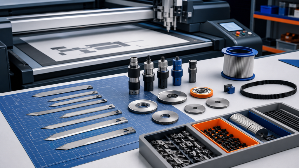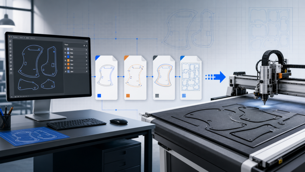

This EVA foam cutting sample test uses real JEKE foam and cut-insert images to explain how a buyer should evaluate the process. The available photographs confirm the type of sample and cutting application; they do not provide a verified speed, tolerance or production-saving figure. Those values should come from a documented test using the buyer’s material.
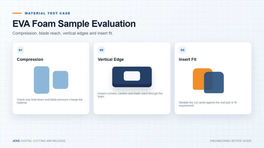
The test question is functional fit, not simply whether foam can be cut
An insert may need to hold a product, protect a surface and remain presentable after repeated handling. Define cavity size, corner shape, minimum wall, visible-face requirement and how firmly the product should fit. Include the actual part or a controlled gauge when possible.
Record EVA construction, density information when available, thickness, laminated layers, surface skin and sheet flatness. A result from one EVA grade should not be presented as universal for every foam sold under the same name.

Stage 1: observe compression and hold-down
Vacuum and tool pressure can compress the foam while the path is cut. Watch whether the sheet bows, shifts or develops visible marks. A dimension measured immediately under compression may differ after the sample recovers, so the report should state when and how the part was measured.
Start with a simple outer profile and one internal feature. The first objective is stable support and complete cutting, not maximum speed.
Stage 2: match blade reach to thickness and geometry
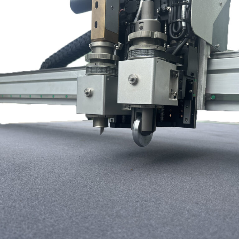
The blade must pass through the material without excessive unsupported length. Inspect whether deep cuts remain vertical, particularly at corners and narrow cavities. Record tool type, blade identification and the cutting surface used under the sample.
Stage 3: inspect the edge as a three-dimensional surface
Look from the top, bottom and side. Check incomplete cut, compressed lip, roughness, corner tearing, undercut and variation through the thickness. Use close-up photographs with a scale reference. If the test changes tool or settings, keep each result identifiable.
| Observation | What to record | Decision affected |
|---|---|---|
| Sheet movement | Hold-down zone, support and orientation | Vacuum and loading method |
| Compression | Condition during cutting and after recovery | Measurement and process setting |
| Vertical edge | Top, middle and bottom appearance | Blade length and tool choice |
| Small cavity | Corner quality and removed-piece release | Minimum practical feature |
| Insert fit | Retention, removal and surface contact | Approved geometry and allowance |
Stage 4: perform the insert fit check
Place the real product or gauge into the cavity. Record whether it enters without damaging the foam, remains secure and can be removed as intended. The fit result can expose an allowance problem even when the cut path followed the digital file correctly.
Translate the result into configuration requirements
The conclusion should state required working area, tool and blade, practical thickness range tested, hold-down method, file preparation notes and any feature needing another trial. Do not convert one acceptable sample into an unsupported universal production rate.
Compare this workflow with JEKE’s EVA, EPE, XPE and sponge cutting guide, foam insert machine selection guide and the CNC EVA cutting machine. To arrange a test using your own foam and insert requirement, send JEKE the material and part file.