Buyer question: How should a packaging sample room organize CAD, cutting, creasing and revisions so prototypes move faster?
Short answer: Use one controlled workflow: confirm board data, prepare the CAD structure, assign cutting and creasing tools, run a small test, inspect folds and dimensions, revise the file, then save the approved parameters. The machine is only one part of the process.

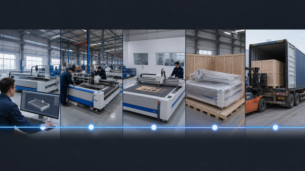
The six-stage packaging prototype workflow
- Collect the board type, thickness, flute direction, printed status and finished-box requirements.
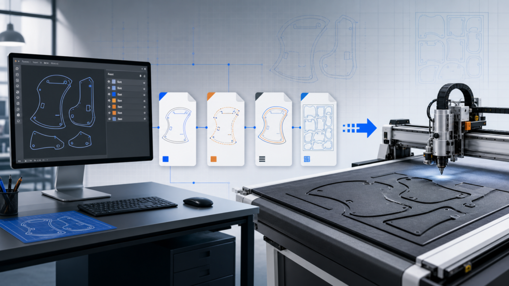
- Prepare or clean the CAD file, confirm closed paths and separate cut, crease, V-cut and marking layers.
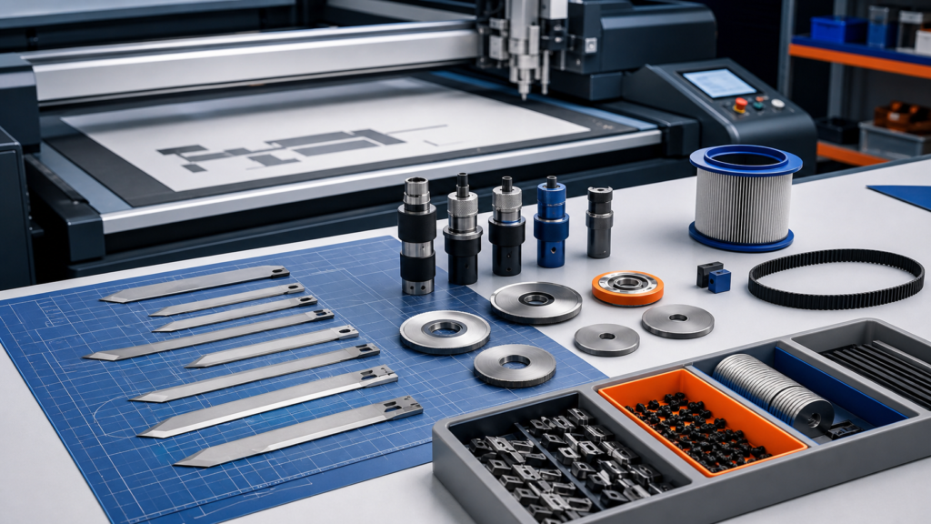
- Select tools and parameters for the actual board instead of copying settings from another material.
- Cut a controlled first sample and label it with file version, material batch and parameter set.
- Inspect dimensions, fold behavior, corner quality, slots and assembly before revising the design.
- Save the approved file, tool assignment and material notes so the next sample is repeatable.
Stage 1: define the material before opening the CAD file
Packaging structures behave differently on corrugated board, folding carton, honeycomb board, foam board and laminated material. Thickness alone is not enough. Record flute type and direction, surface coating, print registration, grain direction and whether the sample must be folded immediately after cutting.
If printed material is involved, add registration marks and confirm whether camera positioning is needed. If the sample is structural only, focus first on dimensions, crease location and assembly behavior.
Stage 2: prepare CAD layers for tools
A clean file separates operations. Through-cut paths, crease lines, V-cut lines, kiss-cut areas and markings should not share the same layer or color without a clear rule. Remove duplicated lines and open paths before the job reaches the machine. This reduces repeated cuts and unexplained tool movements.
| CAD operation | Typical tool | Quality check |
|---|---|---|
| Outer contour and slots | Oscillating or drag knife | Dimensions, corner quality and complete separation |
| Fold lines | Creasing wheel | Fold position, pressure and surface cracking |
| Beveled joints | V-cut tool | Angle, remaining material and joint fit |
| Labels or assembly marks | Pen or marking tool | Legibility and correct layer assignment |
| Printed contour | Camera-positioned cutting | Registration accuracy across the full sheet |

Stage 3: build the first test around risk
The first test does not need to use the entire sheet. Start with the most difficult corner, narrow slot, short crease and critical fold. If those features pass, continue to the complete structure. This saves board and makes parameter changes easier to understand.
- Check whether the knife reaches full depth without damaging the cutting mat.
- Check whether crease pressure creates a clean fold without breaking the printed surface.
- Check whether small waste pieces stay controlled by the vacuum system.
- Check whether the part can be removed without tearing tabs or narrow bridges.
Stage 4: inspect the assembled package, not only the flat sample
A flat sample can look accurate and still fail during folding. Assemble it using the intended tabs, adhesive or locking structure. Measure the final internal dimensions, panel alignment and closure. For inserts, confirm that the product fits and can be removed without damage.
Stage 5: control revisions
Use version names that connect the CAD file to the physical sample, such as project-material-version-date. Record what changed and why. Do not overwrite the approved file with an experimental revision. A simple revision log prevents the operator, designer and customer from reviewing different structures under the same name.
Stage 6: save a repeatable production record
After approval, save the final drawing, tool mapping, material description, blade type, crease wheel, speed, depth and vacuum notes. Photograph the assembled sample and keep the approval message with the job record. The goal is to reproduce the approved result without repeating the full discovery process.
What to send JEKE for a workflow test
- Actual board samples, including printed or laminated versions if used.
- DXF, AI, PDF or other available structure files with operation layers identified.
- Photos of the assembled package and the product or insert it must hold.
- Critical dimensions, fold requirements and the expected number of revisions or samples per day.
- Any need for camera registration, V-cut, kiss-cut, marking or barcode identification.
Recommended next step
Send one representative structure and the real board material for a complete test from file preparation through assembly. Review the process record, not only a short cutting video, before deciding the final machine and tool configuration.
Useful JEKE links: CNC cutter for corrugated cardboard samples · CNC cardboard box sampling machine · Digital cutting machines · Contact JEKE for a packaging sample test
Buyer FAQ
Do I need a physical die for every prototype revision?
A digital workflow can cut revised CAD files directly, which is useful during prototyping and approval. The final production method can still be chosen according to volume and economics.
Why do crease lines crack after folding?
Common causes include unsuitable crease pressure, wheel choice, material direction, coating and fold geometry. Test the actual board and inspect the assembled sample.
Can the same parameters be reused for every corrugated board?
No. Flute type, thickness, moisture, coating and supplier batch can change cutting and creasing behavior. Save approved settings by material specification.