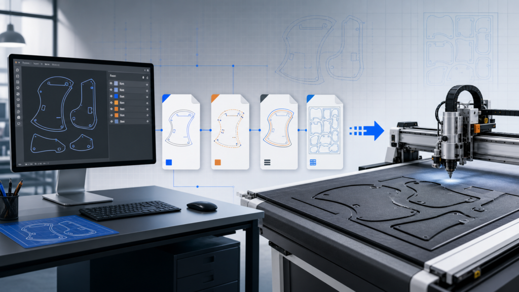
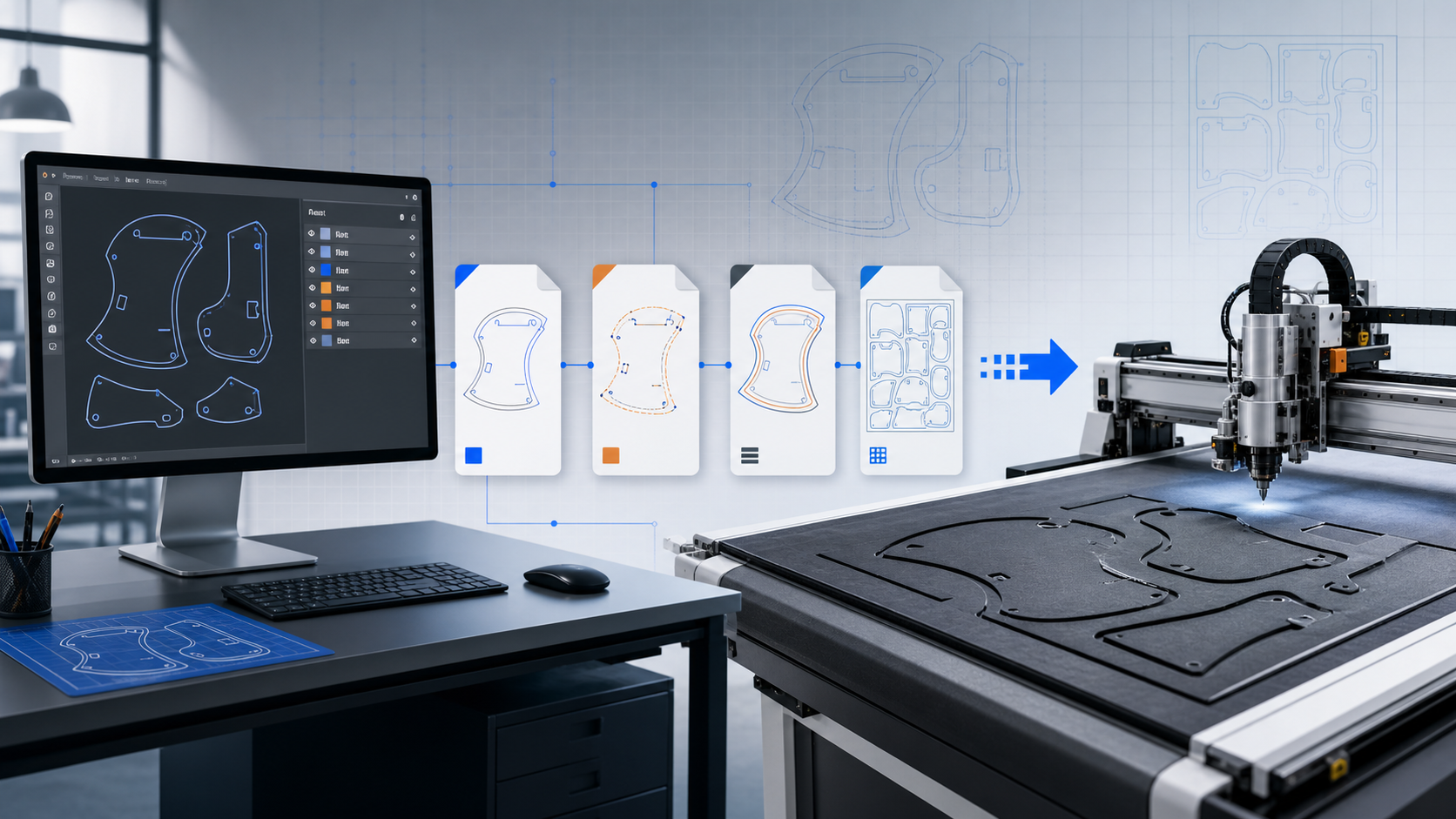
The right CNC cutter file formats depend on both the design source and the software supplied with the machine. A format name alone does not guarantee a production-ready job. Scale, closed paths, duplicated lines, layers and the route from design software to the cutter all need to survive the handoff.
JEKE product pages show different format support by model. Several systems list DXF and PLT, while selected configurations also describe AI or CDR compatibility. Buyers should therefore confirm formats against the exact controller and software package in the quotation.
Design format and machine-ready format are not always the same
A designer may work in AI, CDR or another native application because those files preserve editable artwork. Production software may prefer DXF or PLT for clean paths and job transfer. PDF can be useful as a visual reference, but a PDF containing only a raster image does not automatically provide a cut path.
| Format | Common role | Buyer check |
|---|---|---|
| DXF | Exchange of vector geometry between CAD and cutting software | Confirm units, curve conversion, layers and closed contours |
| PLT / HP-GL | Plotter-style path transfer supported by many cutting controllers | Check scale, path order and software export settings |
| AI / CDR | Editable artwork and design preparation | Confirm whether import is direct or requires an export step |
| Reference drawing or vector exchange in some workflows | Verify that the file contains vectors rather than a flat image | |
| Raster image | Reference, print artwork or camera-recognition source | A cut contour may need to be created separately |
Five file problems that create production errors
- Wrong units: a millimeter file is interpreted as inches or the import loses its scale reference.
- Open contours: endpoints that look connected on screen remain separate paths.
- Duplicated geometry: two paths occupy the same line and cause repeated cutting.
- Unconverted text or effects: fonts, masks or appearance effects do not become usable geometry.
- Mixed process layers: cut, crease, mark and print information cannot be assigned reliably.
Before export, remove hidden objects and duplicate lines, convert required artwork to paths, close contours, state the units and keep process layers obvious. Save a clean master file before creating the machine-transfer version.
Test the complete file path before buying
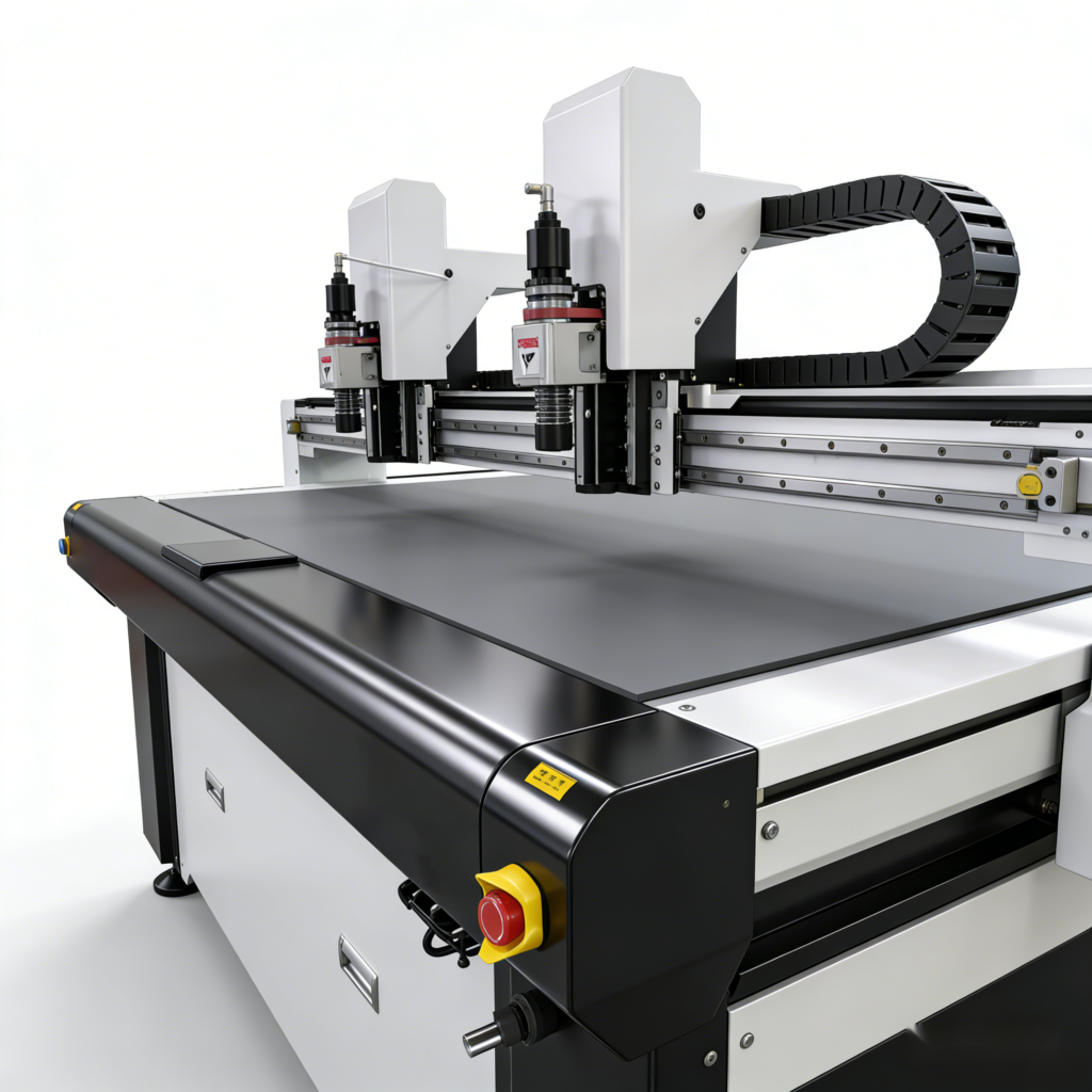
Do not test only whether a supplier can open one DXF. Ask the operator to import the buyer’s real file, assign processes, check dimensions, create a nesting or layout, transfer the job and cut the sample. The test should include a difficult curve, a small opening and at least one repeated part.
For roll material or repeated jobs, verify how the software handles length, copies, nesting and pause or restart. For printed material, add registration marks and contour recognition to the test rather than treating camera work as a normal vector-only job.
Ask for a handoff package, not a software promise
The package should identify included software, supported operating system, import formats, export or controller format, license arrangement, update scope and sample files. Ask who converts an existing customer file and whether that conversion is included in training.
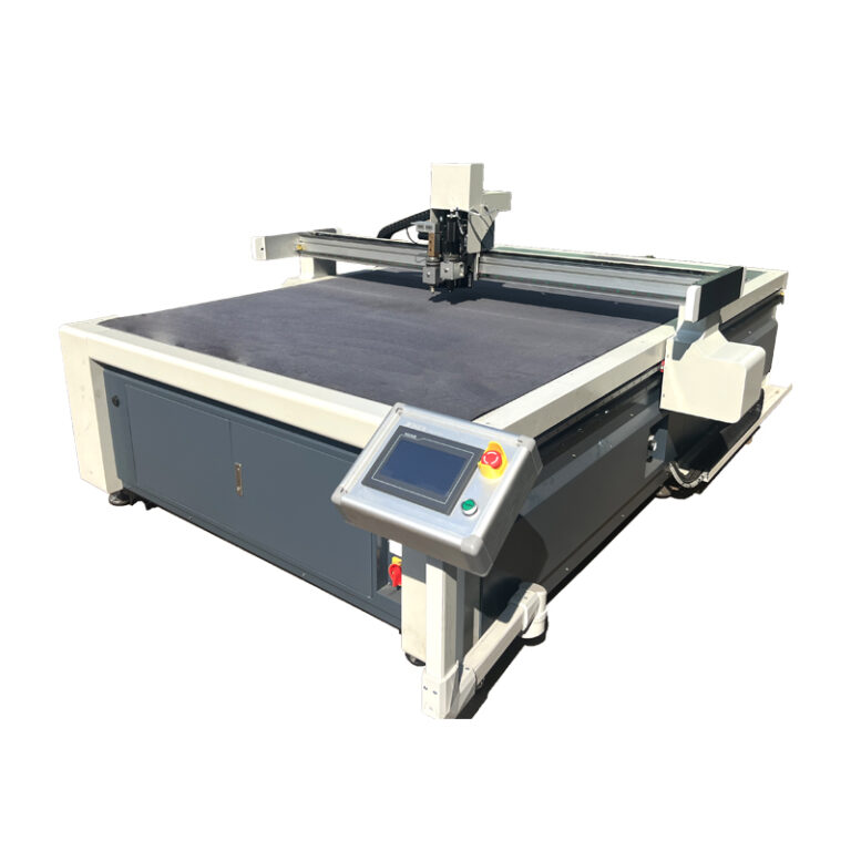
The material testing guide explains how to validate the complete workflow. Buyers can compare the published file information on the JK-1313 flatbed cutting machine and CNC EVA cutting machine. Browse other digital cutting configurations or send a real file to JEKE for compatibility review.