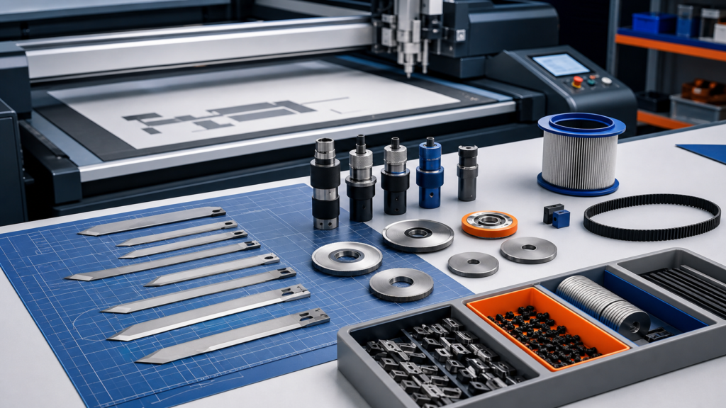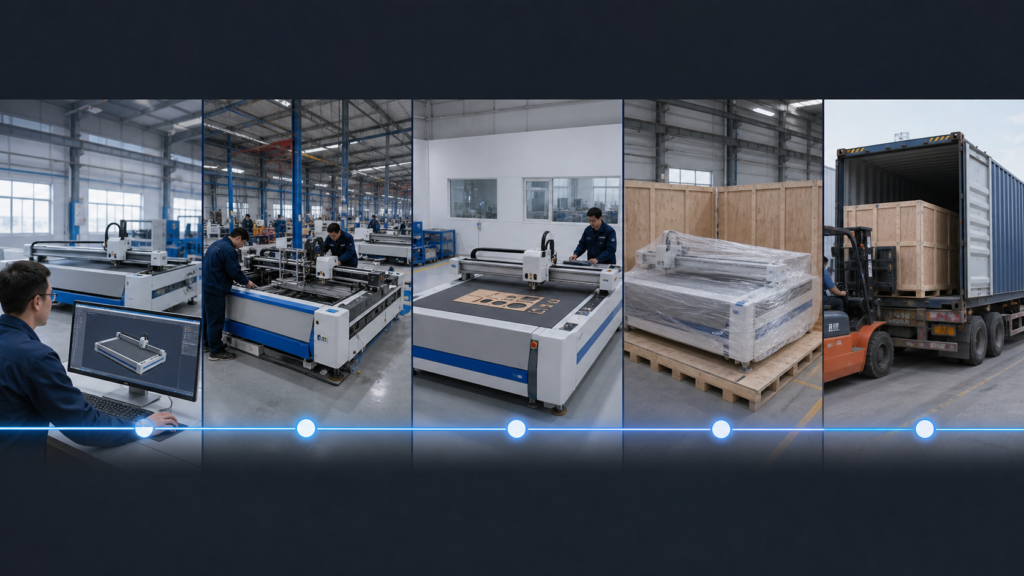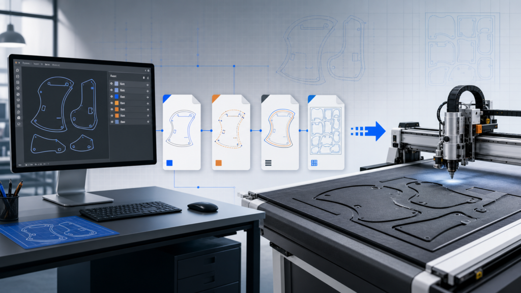
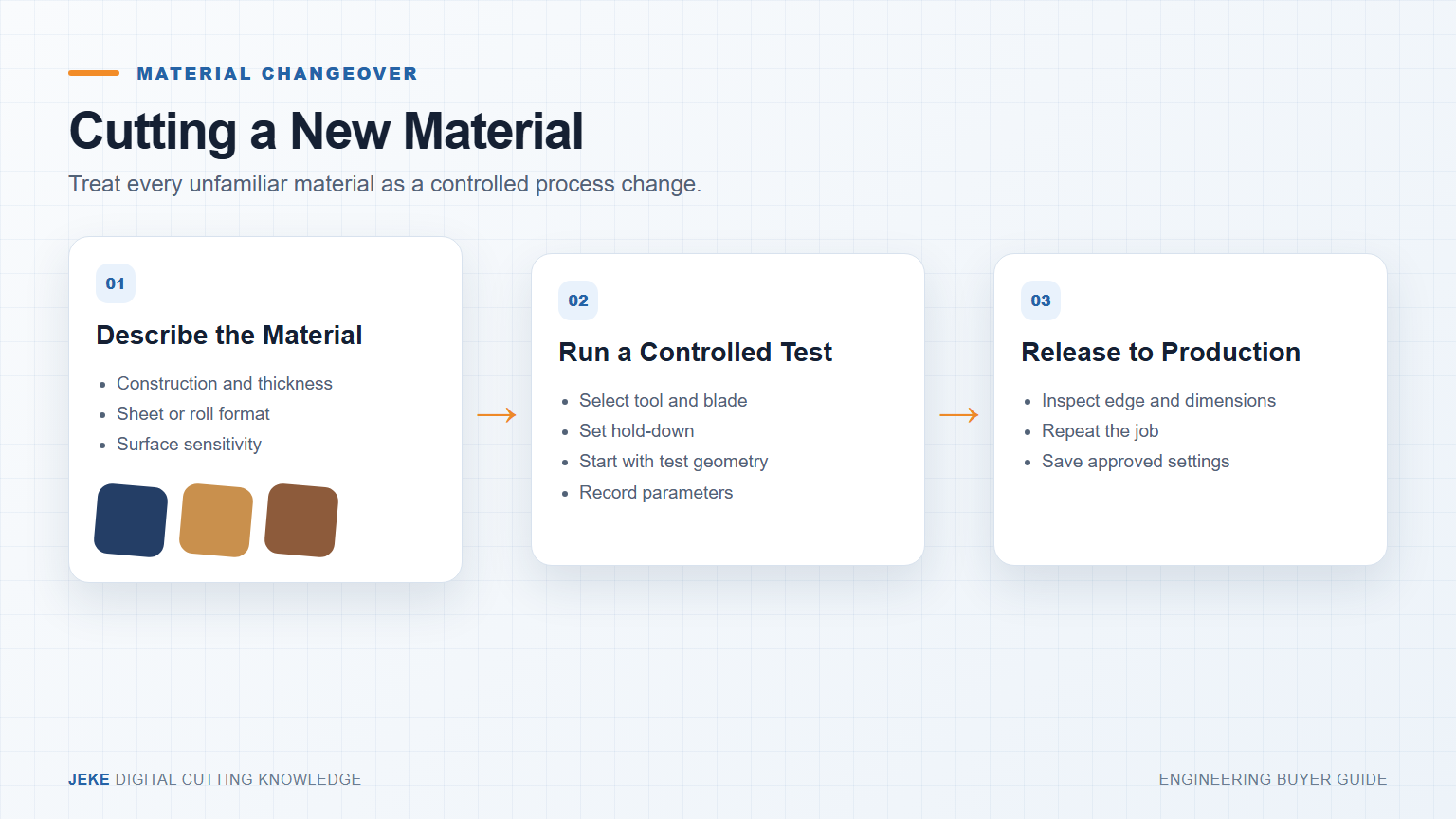
To cut new materials with CNC cutter equipment safely, a factory should begin with a controlled changeover—not a copied speed value. Material construction, thickness, backing, surface, compression and shape requirements determine the tool, blade, hold-down and test method.
Define the new material before choosing a parameter
Record the commercial name and physical construction. Two products both called foam or synthetic leather can behave differently because of density, reinforcement, coating or adhesive backing. Measure thickness in several locations and identify which side can contact the table.
- Is it a sheet or roll, and what is the largest working format?
- Does it stretch, compress, shed fibers or recover after cutting?
- Can the visible surface accept vacuum or handling marks?
- What features matter: small holes, long edges, tight curves, crease lines or printed contours?
- What is the acceptance test: dimension, appearance, fold, fit or assembly?

Screen for process limits before loading the file
Confirm that the material is appropriate for mechanical knife cutting and does not create a hazard for the installed system. Check maximum practical thickness for the selected tool, blade reach, hold-down and whether the material contains hard inclusions or an abrasive layer.
If the material is unfamiliar, send a sample to the supplier or request guidance before running a full layout. Do not assume a tool is suitable because it worked on another material with a similar name.
Select the tool from material behavior
| Observed behavior | Test question | Possible process direction |
|---|---|---|
| Soft and compressible | Can the material be held without deformation? | Review blade reach, oscillating action and hold-down |
| Woven or fibrous | Does the edge fray or pull? | Compare rotary and oscillating options where applicable |
| Dense or rubber-like | Does resistance deflect the blade? | Use a controlled oscillating-tool test |
| Visible surface | Do table contact and vacuum leave marks? | Add protective handling and clean support |
| Printed contour | Does print distortion affect the cut path? | Test camera recognition and registration workflow |

Use a three-step test ladder
First, a safety and motion test: use a small simple path to confirm hold-down, blade reach and clean movement. Second, a diagnostic test: add curves, corners, holes and repeated features. Third, a production-representative test: cut the real part or a layout containing the critical geometry.
Change one main variable at a time. Record the previous setting and observed effect. If several variables change together, the team cannot reproduce the improvement later.

Release a setting only after repeat and inspection
Inspect both sides, corners, internal features and dimensions. Repeat the job in more than one table position where relevant. For roll work, include feeding. Save the approved file, tool, blade, settings, hold-down notes, photographs and date as a controlled material recipe.
Define a stop condition: worn edge, incomplete cut, surface mark, dimensional drift or material movement. Operators then know when to change a blade or return to the test process instead of adjusting parameters without control.
Know when the configuration needs to change
A new material may need only a blade and stored recipe, but it can also expose a limit in tool force, blade length, hold-down, working area, camera or feeding. If the process remains unstable after controlled testing, ask the supplier to review evidence rather than forcing the current setup.
Use the oscillating knife material guide, EOT versus POT comparison and sample testing workflow as references. Review digital cutter configurations or send JEKE the material details and test evidence.